
Press Tools
Press tool and sheet-metal die development, correction loops, tryout support, and production-readiness for automotive and industrial programs.
Toolroom Capability
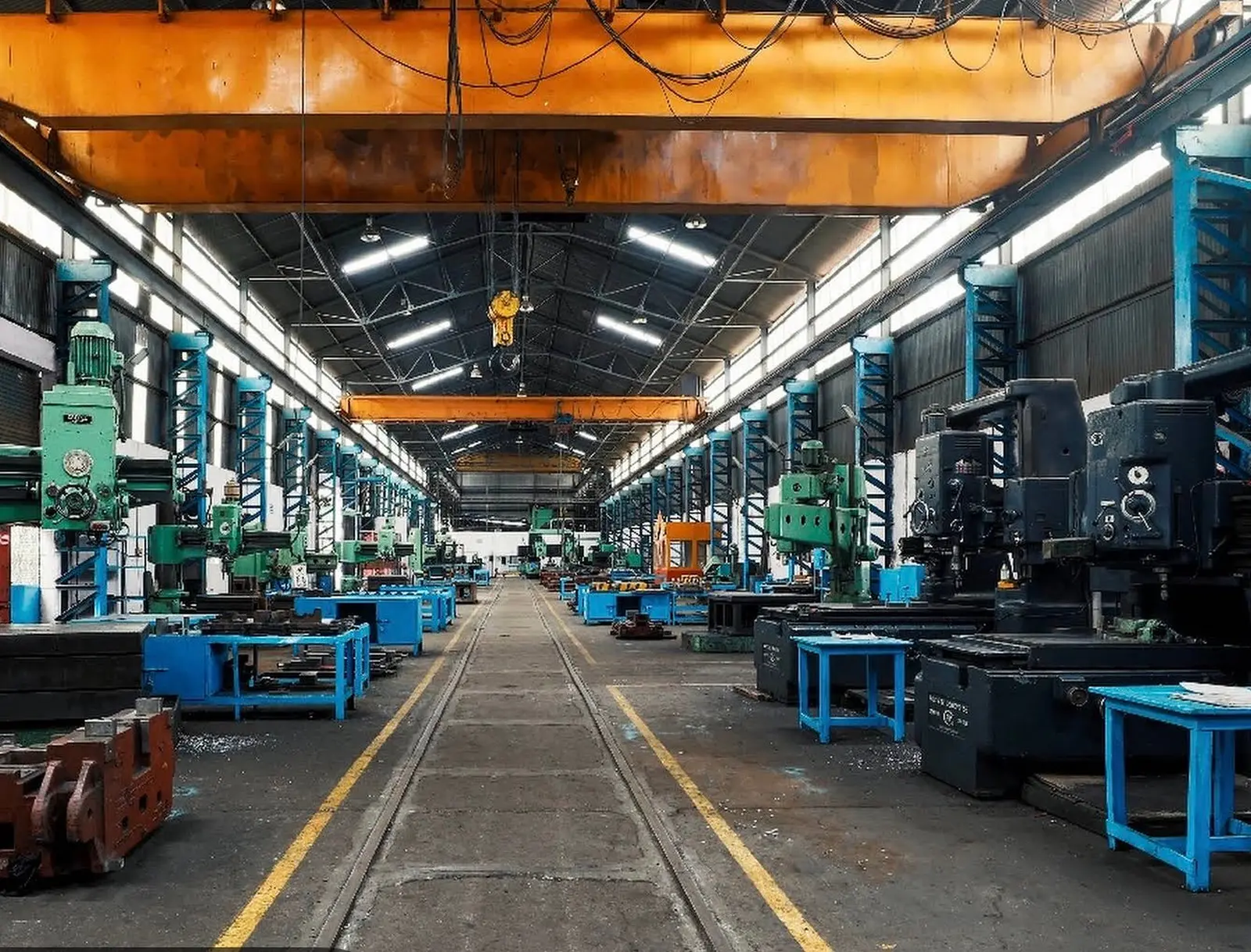
A dedicated Pune toolroom with large CNC machining, press and tryout infrastructure, inspection practice, and project tracking — for press tools, sheet-metal dies, moulds, PDC dies, jigs, gauges, welding fixtures, BIW checking fixtures, and sheet-metal programs.
01 — Core Work
Design input, CAM preparation, large-format machining, finishing, tryout, inspection, corrections, and customer delivery — each job visible in the shop, with clear responsibility as it moves from one stage to the next.
02 — Capability Matrix
Press tool and sheet-metal die development, correction loops, tryout support, and production-readiness for automotive and industrial programs.
Mould and pressure-die-casting work supported by design review, machining, finishing, and shop-floor validation.
Inspection fixtures, welding fixtures, workholding, and gauges prepared for real use on the shop floor.
Specialized sheet-metal components, BIW-related tooling, panels, and fabricated assemblies.
Large-envelope machining, VMC support, plano milling, and conventional machine support for toolroom programs.
Lapping, EDM, grinding, hand finishing, and development press capacity from 300 T to 800 T.
CMM support, inspection documentation, tolerance conversations, and correction feedback into manufacturing.
Stratos, CADMation, and PartLens bring RFQs, CAD review, machine queues, inspection, and delivery status closer to the shop floor.
03 — Capability System
Design and CAM decisions move into machining and finishing, then through tryout, inspection, correction, and customer delivery — with tracking that keeps ownership visible.
CATIA, AutoCAD, AutoForm, part review, tooling intent, and customer requirement clarity.
DelCAM and WorkNC preparation with practical manufacturing constraints considered early.
Large CNC, VMC, plano milling, and support machining aligned to the tool build plan.
Lapping, EDM, grinding, bench work, and toolroom corrections in the same execution rhythm.
Development and trial capacity from 300 T to 800 T mechanical presses for proving and correction.
Stratos brings status, ownership, and delivery risk into daily toolroom review.
04 — Machine Capacity
Usable travel, bed size, column clearance, control, and table load for all seven VMCs — shown the way a buyer reads a plant list.
3D printed checking fixtures solve a real delivery problem: how to inspect sheet-metal parts consistently when time, cost, and manpower are under pressure.
BIW checking fixture development FDM-based fixture programs · in-house design features · practical inspection use05 — Checking Fixtures
3D printed BIW fixtures for sheet-metal inspection — useful when fixture volume, timeline, and cost make conventional routes too slow or resource-heavy.
High-volume checking-fixture requirements delivered within a month when the program window demands it.
Printed parts positioned around practical accuracy expectations, with post-processing only where it adds value.
In-house build volume in mm; larger fixtures split and aligned with dowels, built-in features, or threaded brass inserts.
06 — Quality Checks
Quality reports, tolerance checks, and dimensional findings kept close to correction and customer review.
Founder-led management, toolroom leadership, and manufacturing teams keep responsibilities visible.
Design, CAM, CAD/BOM work, and drawings treated as production inputs, not back-office paperwork.
Stratos, CADMation, and PartLens support project tracking, CAD review, shop-floor checks, and inspection records.